Portfolio
Mickael Renault
Sensors and Algorithm Engineer

Home > Engineering > Motion and gesture analysis from a Magnetic and Inertial Measurement Unit (MIMU)

Context
Abstract
This document details the processing chain that transforms biased data from a low-cost Magnetic and Inertial Measurement Unit (Magnetometer, Accelerometer, Gyroscope) into real-time motion estimation and how these data can be used for a complete gesture analysis.
Calibration of the sensors (Chapter I), is a crucial requirement for a more accurate orientation and displacement estimation (Chapter II), that we choose to develop with our own Sensor Fusion algorithm. Eventually, this all-purpose motion tracking system will be specifically placed into the context of golf to be used for swing detection and gesture analysis (Chapter III) in a way to extract and collect meaningful data for golf players.
Please feel free to contact me for any questions
Keywords
MEMS, MIMU, Sensor Calibration, Sensor Fusion, Dead Reckoning, Data Analysis
Technical report
| Title | Motion and gesture analysis from a Magnetic and Inertial Measurement Unit |
| Provisional patent | US#62/557,225 |
| Inventor | Mickael Renault |
| Host company | Game Your Game, Inc. |
Results
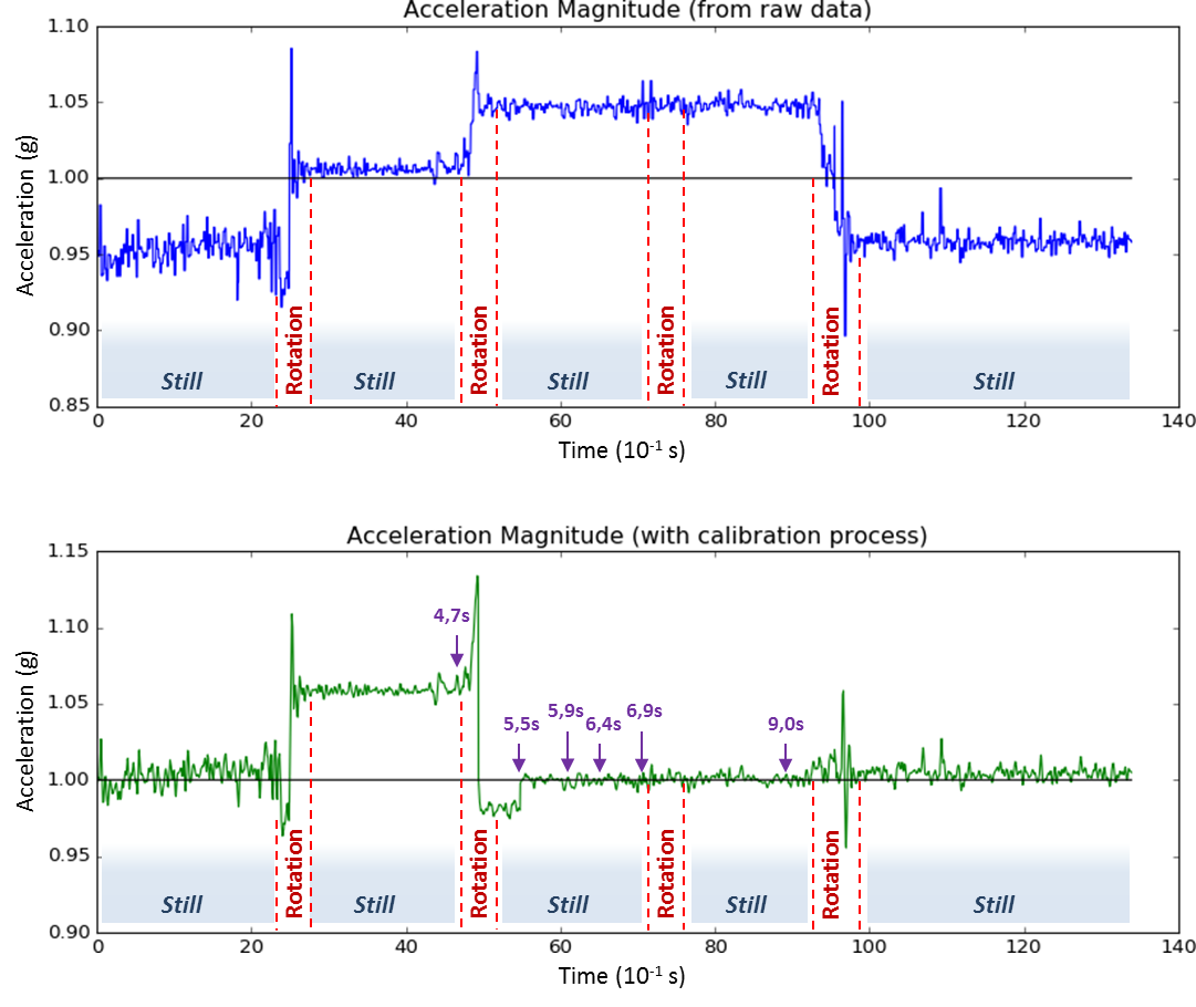
Accelerometer calibration
Acceleration at rest is expected to be 1g (gravity) in vertical direction. However, when rotating the Accelerometer to test every axis (X, Y, Z), we can observe that the actual measured acceleration is far from the ideal 1g. Here we have clearly a 5% error that will be corrected with the calibration process.
After a few iterations of the algorithm, error drops down to under 1%. In real-time, it will take less than 10 sec.
Gyroscope calibration
The direct consequence of a good calibration process for the Gyroscope is to properly compute an estimation of the rotation of the device. In other words, if the raw data are noisy and biased (which is often the case for low-cost IMUs), it will be impossible to guess the orientation of the board.
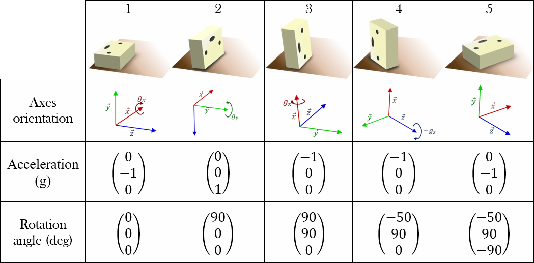
In the following test, based on a known initial state, we rotate the device several times. We anticipate every intermediate state, and fill a table with expected results.
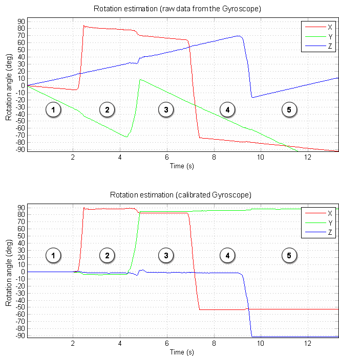
Before calibration, integration of the angular velocity will not provide a realistic resultant rotation.
After calibration of the gyroscope, the same integration will show a way more accurate state of the device and its orientation.
 |
 |
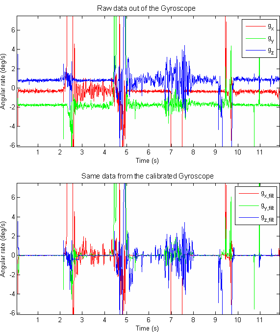
Another illustration of the gyroscope calibration process is to have a look at the following graph, comparing raw data and calibrated data from the sensor. We can see that this model has a very fast convergence in real-time processing (under 200ms on a Cortex-M4 processor).
Magnetometer calibration
Real time magnetometer calibration: raw data are describing a tilted shifted ellipsoid, that we can detect while the device is in motion. When the model is correctly defined, calibration parameters are updated and all the points that follow are fitted on a sphere. Any magnetic disturbance is still detected and will be processed appropriately over the next steps of Sensor Fusion.
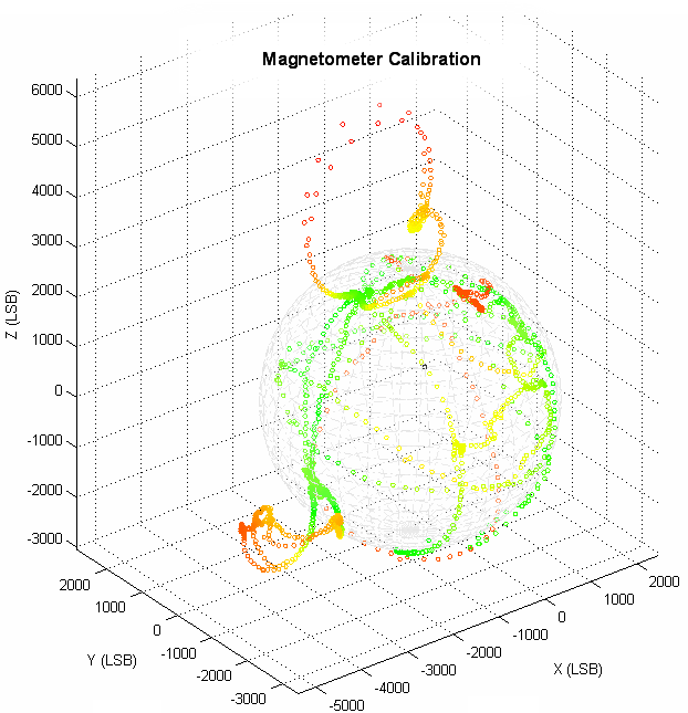 |
In this graph, we are showing the ability of the calibration algorithm to provide a strong reference for accurate magnetic mesurement. Relying on this model, every magnetic disturbance (magnet close to the board) is detected and discarded (red points). Features of the Magnetometer calibration algorithm:
|
Magnetometer calibration - live demo
Sensor Fusion
The "fusion"of the three sensors (Accelerometer, Gyroscope, Magnetometer) is the base for a reliable estimation of the orientation of the device in real time.
Each sensor has its own strengths and weaknesses, and when together, one can compensate the weakness of the other.
- Accelerometer: can give the direction of the gravity vector, but only when the motion level is low
- Gyroscope: can provide an estimate of the rotation angle of the system in a short period of time, but the bias is increasing rapidly
- Magnetometer: can provide a reliable reference in the Earth system, but is sensitive to magnetic disturbance and doesn't always have a high rate capability.
|
+1.617.259.7985 |